State Diagram For 4 Bit Counter
Counter bit ripple binary clock trigger question edge will transcriptions count Counter bit state diagram flip binary using circuit flops table truth draw ff construct let Flops implementation
Solved: Chapter 7 Problem 4E Solution | Contemporary Logic Design 2nd
Counter bit gray code diagram state consider figure Ring counter bit verilog code vhdl diagram example tips testbench ckt tricks coding written 4 bit down counter
[solved] question 04: design a 4 bit binary ripple counter that trigger
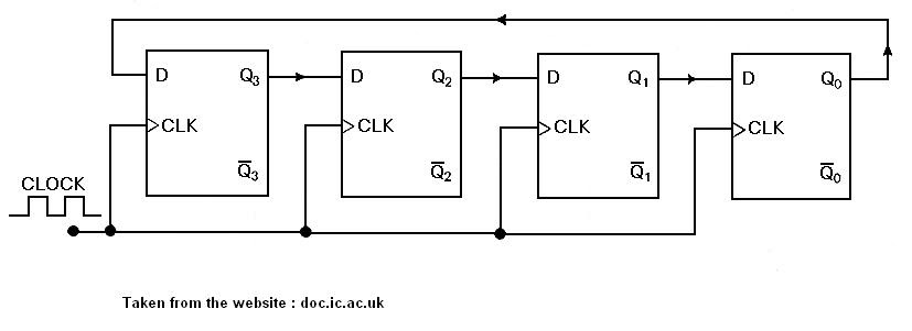
Circuit design of a 4-bit binary counter using d flip-flops – vlsifacts4 bit up down counter truth table Circuit design of a 4-bit binary counter using d flip-flops – vlsifactsBit 4bit counters.
4-bit binary counter with parallel load.Solved: chapter 7 problem 4e solution Parallel binary logicVhdl coding tips and tricks: example : 4 bit ring counter with testbench.

Bcd counter circuit using the 74ls90 decade counter
Counter bcd mod diagram state circuit decade flip 74ls90 digital using flopsState diagram and implementation of a six bit ring counter with d State diagram for the mod-11 synchronous counter.Counter bit down circuit diagram digital.
Counter bit flip using binary flops circuit output q3 final .


Solved: Chapter 7 Problem 4E Solution | Contemporary Logic Design 2nd

BCD Counter Circuit using the 74LS90 Decade Counter
VHDL coding tips and tricks: Example : 4 bit Ring Counter with testbench

4-Bit Binary Counter with Parallel Load. | Download Scientific Diagram

State diagram for the MOD-11 synchronous counter. | Download Scientific

4 Bit Down Counter

4 Bit Up Down Counter Truth Table | Letter G Decoration

State diagram and implementation of a six bit ring counter with D
![[Solved] Question 04: Design a 4 bit binary ripple counter that trigger](https://i2.wp.com/www.coursehero.com/qa/attachment/13242246/)
[Solved] Question 04: Design a 4 bit binary ripple counter that trigger